Electrical appliances and applications pass through the entire building – from the technical area through corridors and vertical shafts up to living accommodation. The risks from lightning strikes, surge voltages and the spread of fire to electrical installations are often underestimated, and the obligation to keep the building systems such as control cabinets, luminaires or cable trays up to date with a required protection against dust and humidity is carried by the owner or the landlord. This requires a sheet metal application that is not combustible and ensures a long lifetime for the product.
 Cable Trays
 Electrical Enclosures
 Cable Trays
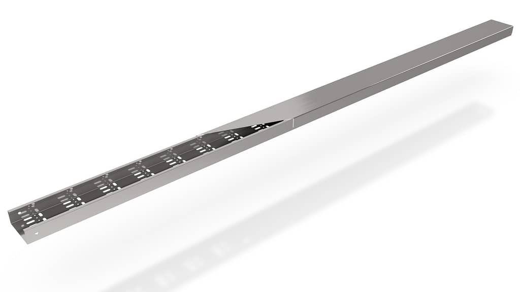
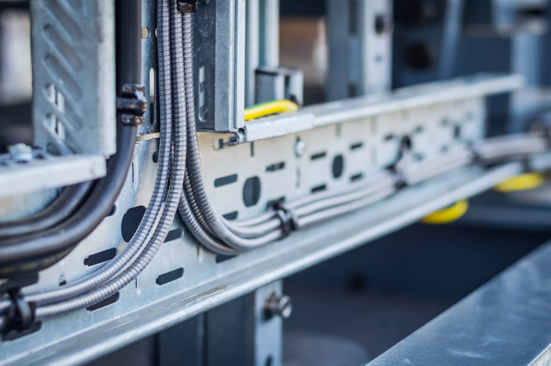
Cable trays and power channels are used to guide and support power and data cables throughout buildings in vertical shafts, stairwells, corridors, and even as underfloor installations. The products are solid or mesh cable trays depending on the purpose, and are made of sheet metal, steel wire, plastic or other combustible material.
The most commonly used cable trays for industrial environments are solid sheet metal with continuous side perforations for fastening, or mesh metal wire with wall brackets. For building installations the underfloor sheet metal systems guarantee safe, flexible cable routing in screed or concrete.
CHALLENGES AND REQUIREMENTS (CABLE TRAYS)
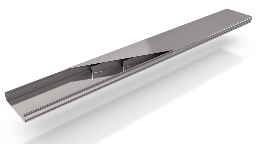
Cable trays of sheet metal plates include the airborne and underfloor solid applications. A finished products consists of the body profile, cover plate and support plates or spacers. In addition to the longitudinal frames there are also intersection pieces of several types. In addition to the sheet metal materials’ fire resistance rating, the underfloor cable trays are also required to be dust-proof with an IP6X rating, which is typically achieved by no punched holes and a snap lock cover to the body.
Process and Material
Cable trays are used in every industrial and commercial buildings, and typically the indoor applications are between 0.5 to 2.0 mm / 25 to 14 GA mild steel or aluminium. For high corrosion areas, such as sanitary areas, spas or outdoors, stainless steel cable trays must be utilized. With a heavy total volume, typically 100 000 to 500 000 meters / 62 to 310 miles per year, the most savings or best cost-per-part (CPC) comes from reducing material thickness while retaining appropriate rigidness. The body rigidness should be improved by peculiar side profile designs of the body. The cover plate is usually thinner material than the body to begin with.
The production requirement for the body profiles and cover plates is roughly 3 parts per minute, usually either 2000 mm / 78” or 3000 mm / 118” long parts. The precise required length is manually processed on the site by handheld cutters. Cable tray widths vary from 50 mm / 1.9” to 800 mm / 31”, with standardized widths every 50 mm / 1.9”. The width and height differences of a body profile is determined by the amount of power cables or data cables to be included within. The series sizes are 20 to 30 parts minimum that will be run straight to a storage.
Punching
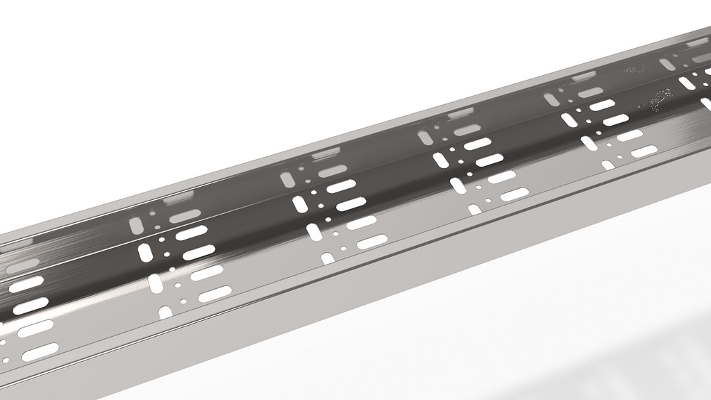
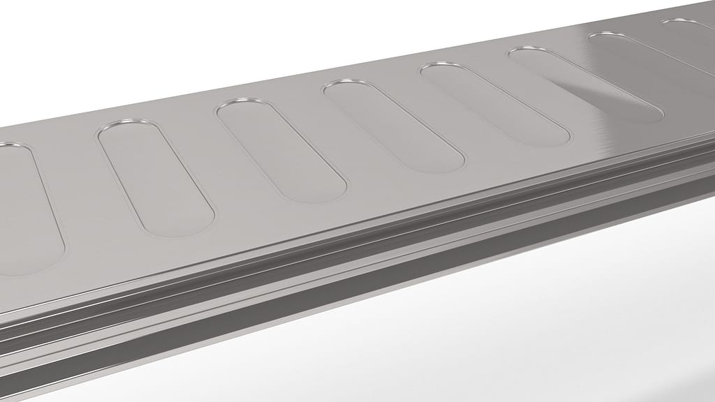
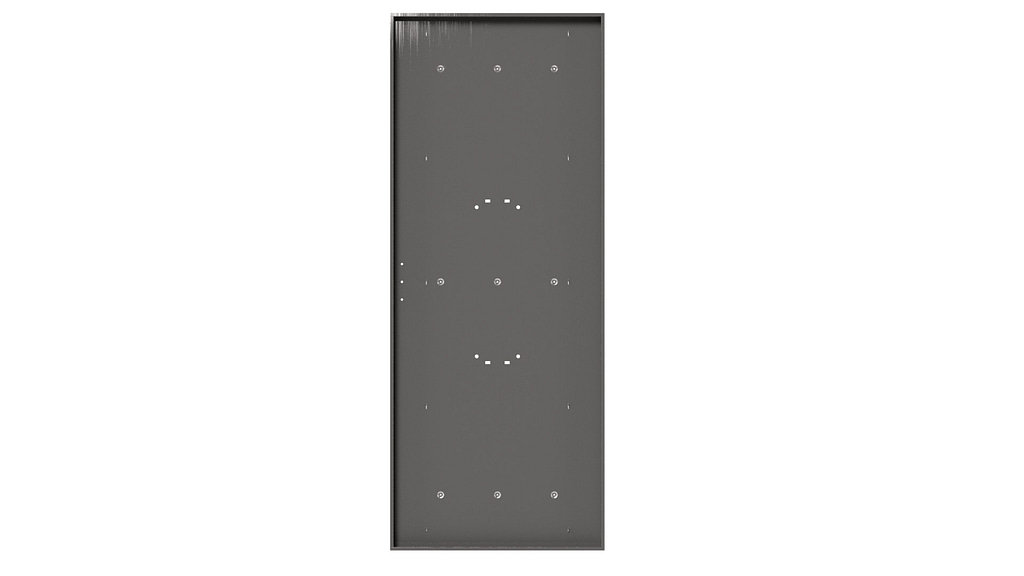
The challenges for punching airborne sheet metal cable trays are several holes and hole patterns for body rigidness that requires an efficient punching line with short cycle times, preferably under 18 seconds. The underfloor cable tray bodies need to have certain embossing’s to withstand the weight of the concrete floor.
Bending
The challenges for bending comes from the most thick cable trays from 1.5 to 2.0 mm / 16 to 14 GA. For the standard length of 2000 mm / 78” or 3000 mm / 118” , many machines can’t perform complicated profile bends with the material thickness. A small bottom width of cable trays leads to difficulties when feeding or manipulating the part. The bending angles needs to be precise as cable trays are installed back-to-back.
Integrations or other functions required for the cable tray manufacturing are traceability markings or the equipment for spacer manufacturing. A very challenging body profile can require several sheet metal machines in a process, and preferably a complete set of all the required parts of a cable tray kit should be packaged ready for delivery.
SOLUTION (CABLE TRAYS)
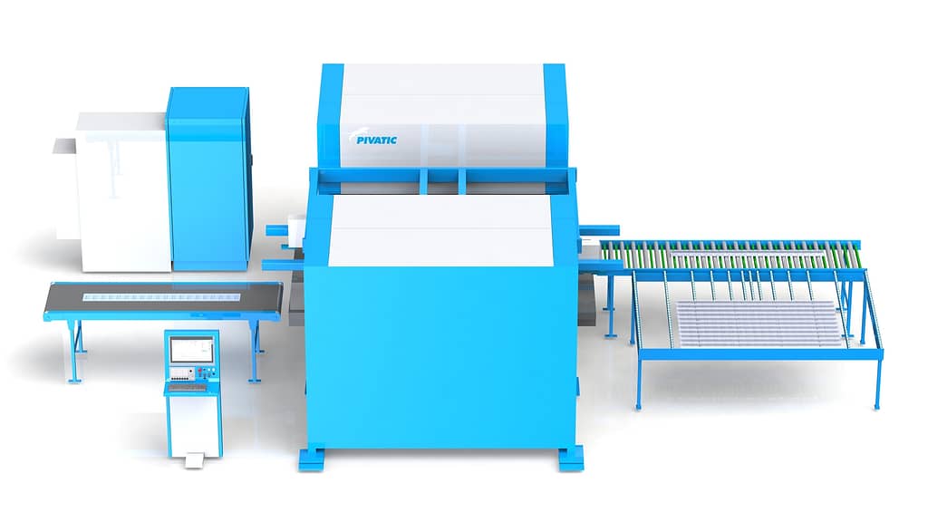
With Pivatic punching and bending solutions you can manufacture all of the cable tray kit parts with a single line. The highly automated machine combinations are capable of 16 seconds per body profile produced, starting from coil material or blanks. Several references from using explicit embossing’s’ or product design changes through consultation can reduce material thickness required by up to 30%, saving you roughly 2.2m€ in a 300 000 meters yearly volume production.
For producing different size body profiles, cover plates or other parts, Pivatic suggest using part-wide coils or one wide coil for all of the parts. The large number of holes in airborne cable trays can be punched with a combination of flexible Thick Turret punching station and a press tool station. When using one coil for all of the parts, the total production run can be nested on the coil and split with widthwise and longitudinal shears.
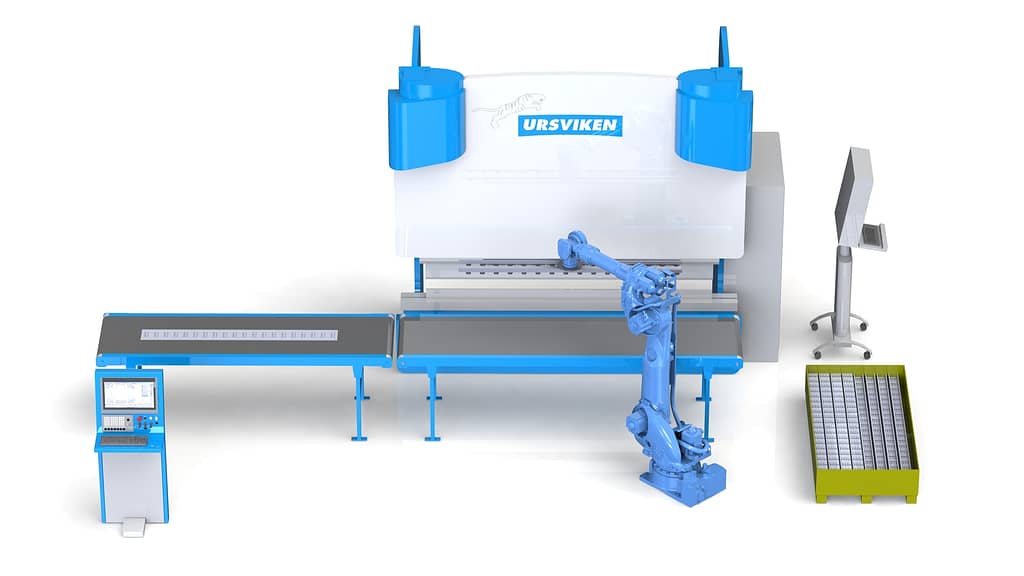
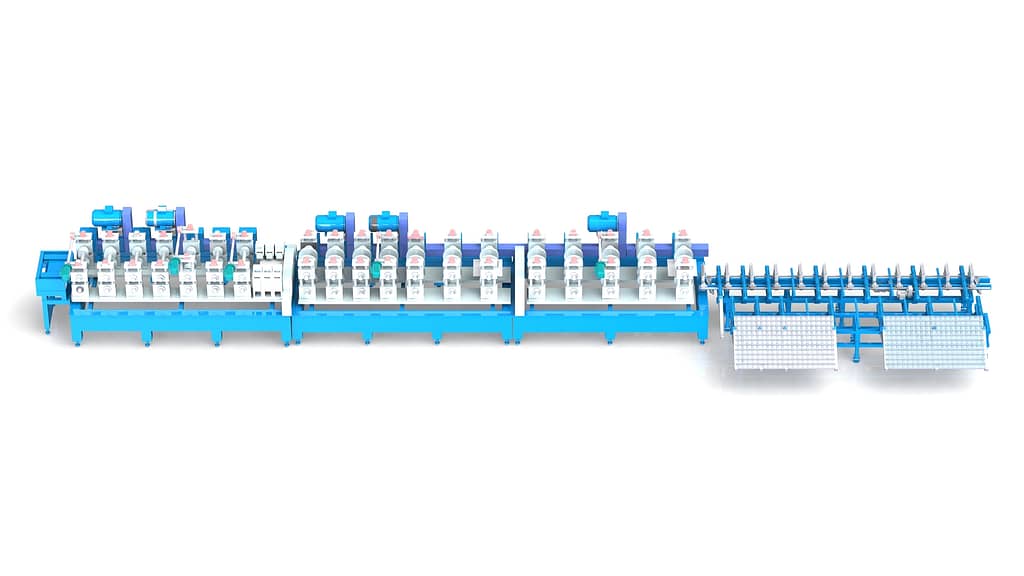
The cable tray body profile bending can be done by Pivatic with several methods, depending the minimum bottom width of the body. Cable trays under 100 mm / 4” bottom width will be done by an integrated press brake, a thicker material with over 100 mm / 4” bottom width will be done with Pivatic wing bending solutions, and the most demanding designs will be bent by Pivatic MPB Multitool bending technology. Simple profiles with no demanding material thicknesses can be done by an integrated roll former.
If an integration for a laser marking device, inkjet printer or a labeling is needed for traceability, these can be added to the line solution. For spacer manufacturing in the same line as body profiles or cover plates, a TOX press can be included alongside the flexible Thick Turret punching and press tooling. Pivatic complete delivery can also be made to include a robot cell for transporting finished parts to a cardboard box and adding lashing straps.
 Electrical Enclosures
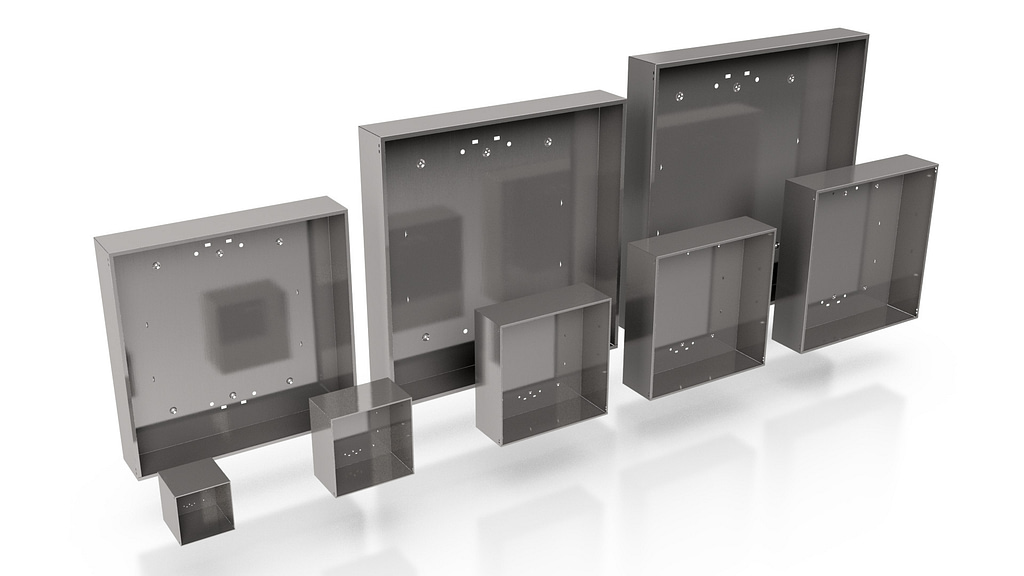
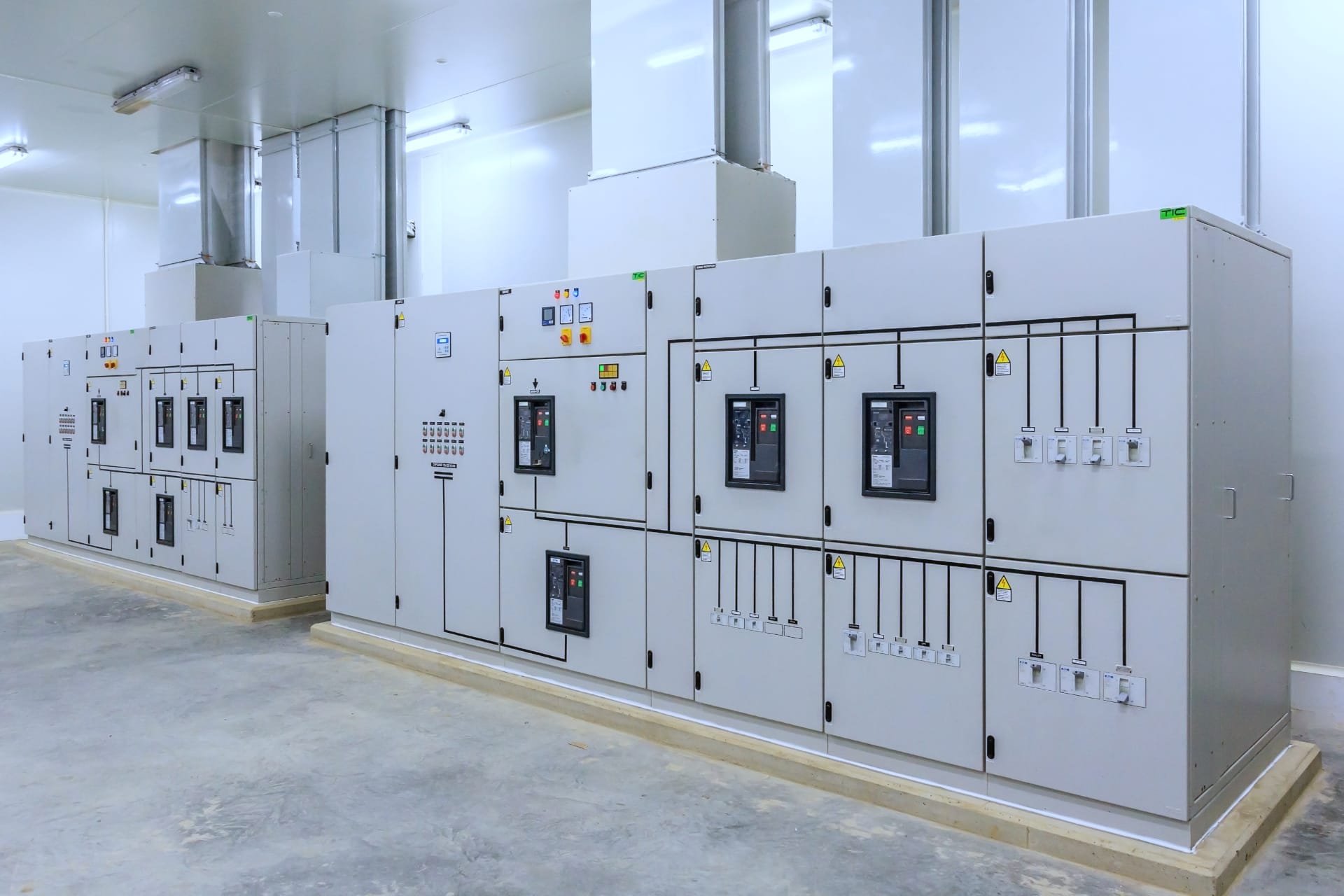
Electrical enclosures are installed and stationed in every domestic and industrial building, cruise ships, and outdoors. They are titled with many names depending on their purpose, such as control enclosures, telecommunication enclosures, transformer enclosures, substations, junction boxes and switch gears. The enclosure sizes vary by the amount of required electrical component installations inside. The demand for small enclosures is high as they can be installed as side-by-side sets.
Manufacturers sell their products either directly to their customers or wholesalers. The order size for direct customers is typically between 1-10 enclosures that has direct contact with series sizes in production.
CHALLENGES AND REQUIREMENTS (ELECTRICAL ENCLOSURE FRAMES)
There are several ways of producing electrical enclosure frames, and all of the methods have their specific requirements for the process.
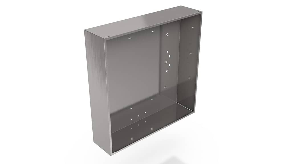
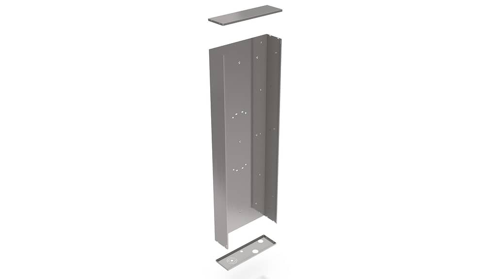
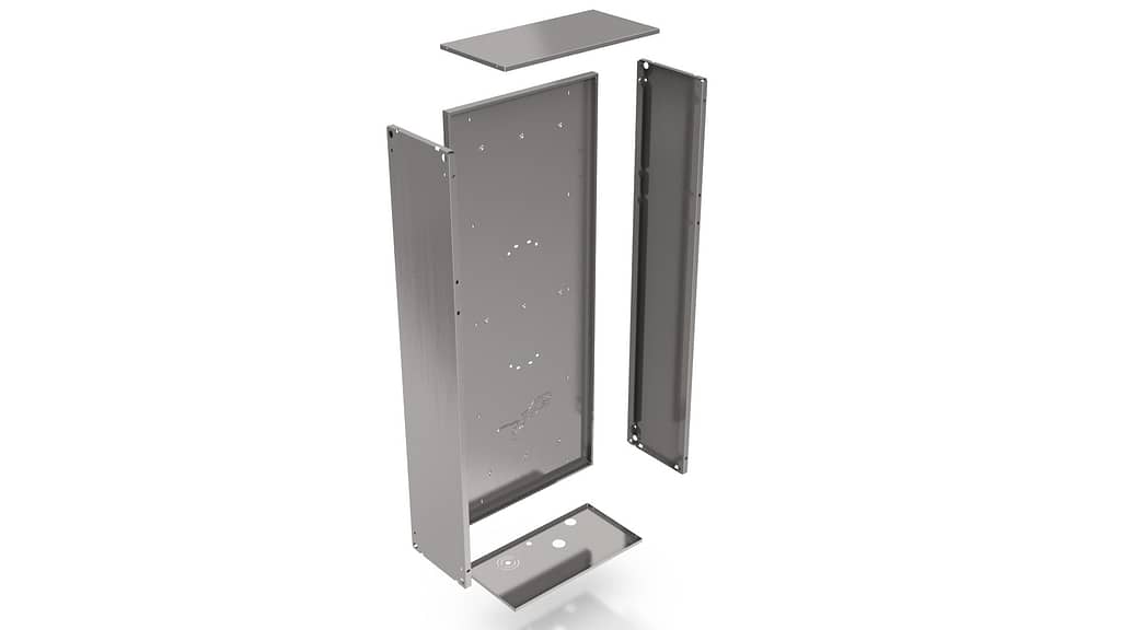
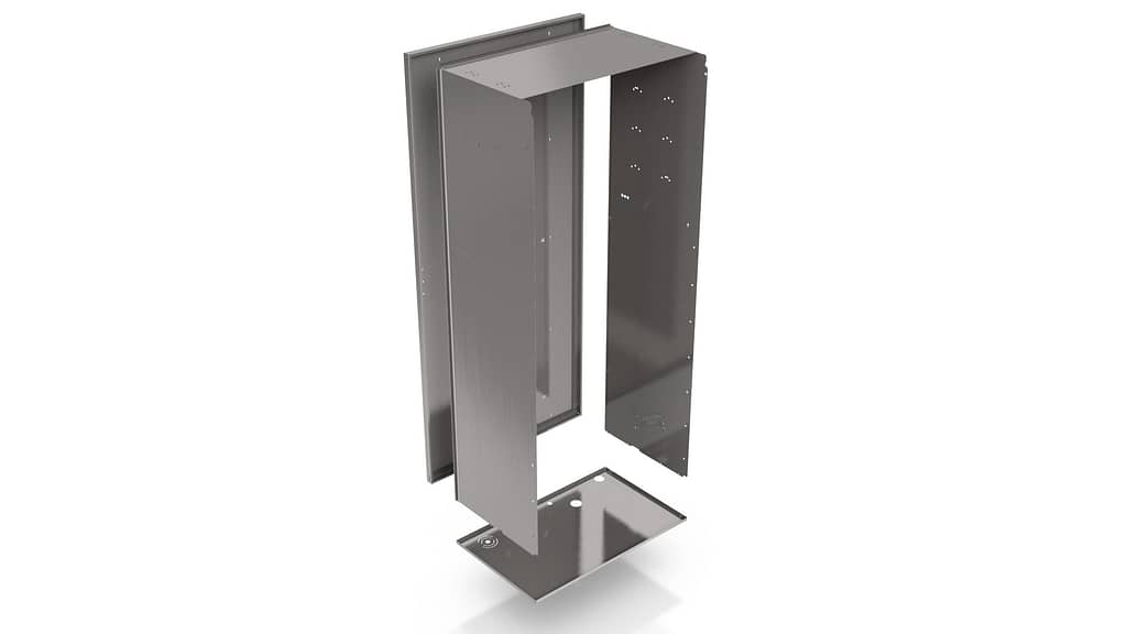
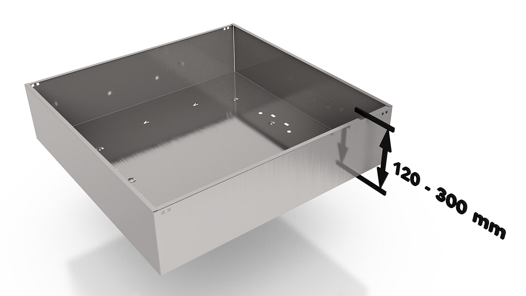
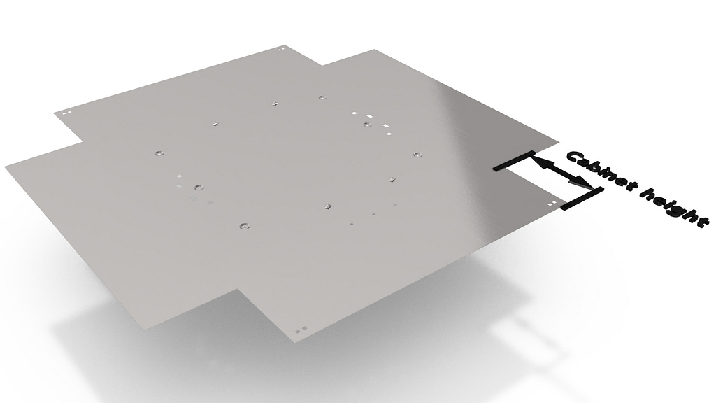
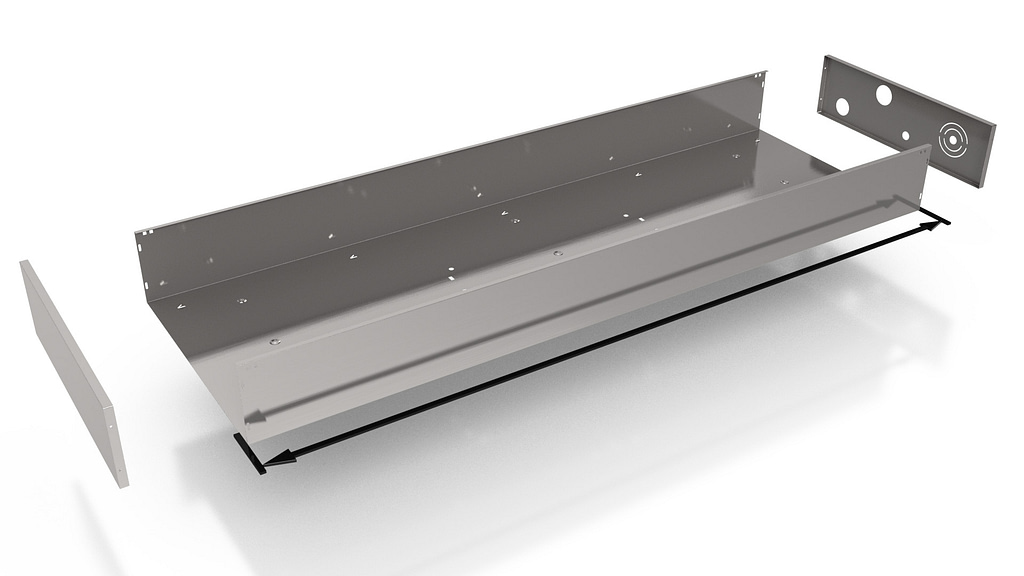
- One-plate box: a single blank to bend the frame, using the back plate as bottom and bending the sides and top + bottom. To bend all sides to the back plate requires corner notches to match the enclosure depth, and the bending machines have a required daylight opening for finished frame removal.
- Profile-frame: a single blank for the back plate and the sides, with top and bottom parts attached afterwards. The enclosure width is standardized and is suitable for mass production with variable enclosure height.
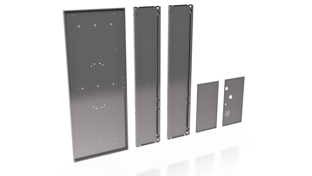
- Mounting plate kit: all sides manufactured as separate panels that are attached to a mounting plate. Requires a flexible single-part production process as all of the parts are manufactured and delivered as assembly kits directly to the customer or electrical contracting business.
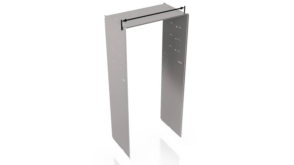
- U-frame: a single blank for the top and the sides, to which the back plate is attached afterwards. A viable production method when enclosure width is not standardized.
Process and Material
A common matter for the methods is not producing the bottom plate in the process. It is typically from a stronger material than the enclosure frame due to knockouts for cable entries. Apart from sheet metal production, the smallest enclosures can also be plastic-casted or deep-drawn metal boxes with sealing recesses at the edges. However, when using frequency converters, it is required to use a sheet metal enclosure to reach a certain EMC -level (Electromagnetic Compatibility) without interference.
Electrical enclosures have IP (Ingress Protection) or NEMA (National Electrical Manufacturers Association) requirement against dust, water and air to isolate the electrical components, and they also have an IK (Impact Protection) rating against external collisions or explosions. For minimum IP rating against dust and water the part attachment can be made with quick and easy spot welding or clinching. For a higher IP rating the attachments and corners can be glued, welded all-around or even molded. A enclosure with molded corners is a challenge for the process but more pleasing to the eye. The required IK rating is achieved by using 1.5mm / 0.059” or thicker material steel instead of a plastic enclosure. Wall-installed enclosures have lesser IK requirement than floor-installed enclosures.
The production volumes are high only for standardized wholesale enclosures and have demanding cycle time requirements as large batches. All others enclosures are manufactured made-to-order for direct customers in small series. Material used for the enclosures vary from 1.00 – 2.5mm / 20 – 12GA thickness of galvanized steel, stainless steel or aluminium. Galvanized and aluminium enclosures are used indoors where the humidity is low. Stainless steel enclosures are used in high humidity areas like outdoors and swimming areas for the corrosion resistance, and also in sanitary facilities due to easy cleaning. There is no requirement for a scratch-free process as the end-product will have corner welding or molding included. Finished enclosure frame will be painted before or after assembly.
Product Sizes
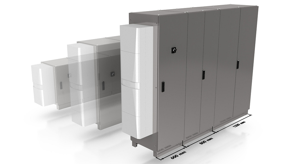
For floor-installed industrial enclosures the widths are standardized, either 600mm, 800mm or 1200mm (23.6”, 31.5” or 47.2”). To have more required enclosure space the solution is typically to have several enclosures installed side-by-side without the partition wall. Height variations are not standardized and are from 800mm / 31.5” up to a service-friendly level. For wall-installed smaller enclosures size variables are from 150mm / 5.9” upwards in width and height. The depth requirement for both enclosure types is according to the electrical installations inside, which of the transformer size determines the need. This is usually from 120mm / 4.7” to 300mm / 11.8”. The side panels can also be used as inspection or service hatches if the enclosure depth allows it.
Punching
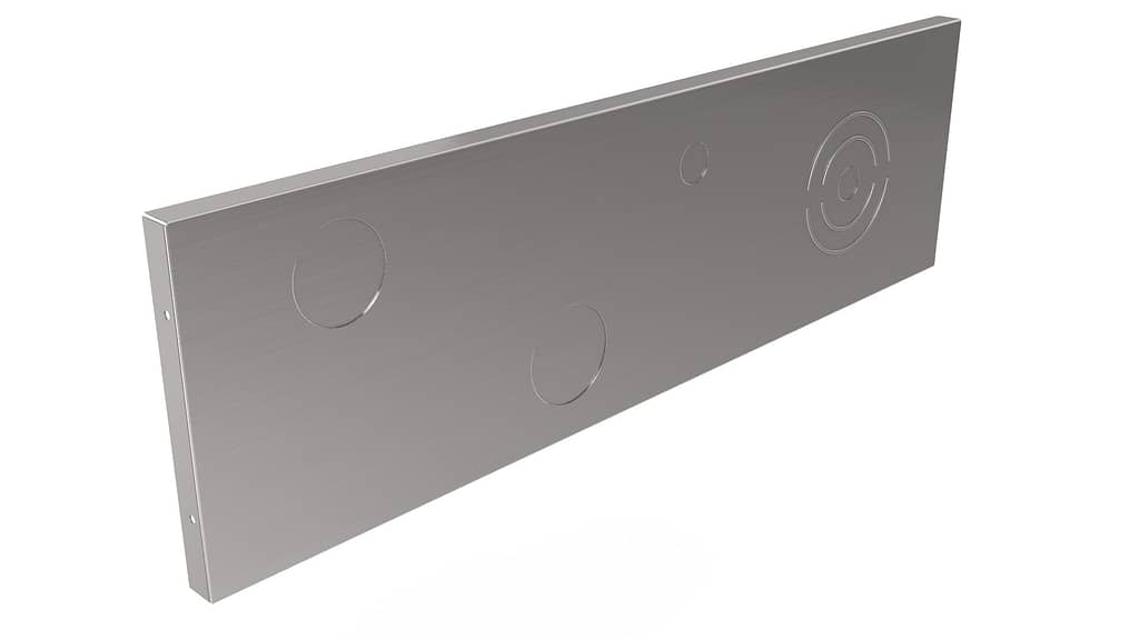
The challenges for punching vary by the production methods. With one-plate box manufacturing, the corner notches translate as enclosure depth and requires a large punch, laser or shear solution. For wall-installed cabins the back plate requires holes and embossing’s for mounting. The sides may have holes for the door hinges or clinching tabs for top and bottom installations. The bottom plate typically has knockouts required for the ease of cabling which need to be pre-cut or formed.
Bending
The challenges for bending are the variable part sizes and small series production. The bends are not complicated with only one or two upward-bends and rarely a Z-bend for door insulation. The one-plate box and mounting plate kit production require a high flexibly solution where every part can be different size.
The profile-frame manufacturing and U-frame manufacturing are more forgiving for the process and only require flexibility in one direction (enclosure height in profile-frame manufacturing, enclosure width in U-frame manufacturing) and a sufficient daylight opening. The U-frame process requires a box bending machine and connectivity to the welding line for back plate attachment.
Apart from punching, forming, cutting and bending, it is also beneficial to have integration possibilities to external processes or machines. These are for example automatic order management software and machines for corner molding, welding, painting and end-product assembly.
SOLUTION (ELECTRICAL ENCLOSURE FRAMES)
Pivatic has developed and delivered suitable solutions for all of the mentioned production methods. The automated line solutions are best suitable for profile-frame and mounting plate kit production as the part volumes, part sizes, and cycle times fit best for a fully automated punch + bend solution.
Pivatic lines can process all of the mentioned materials; galvanized steel, stainless steel and aluminium. All of the production steps are handled from raw material processing, punching, bending, and corner finishing by welding or clinching– all the way up to assembling.
The electrical enclosure frame product design variables are resolved regarding the customers’ production method, series sizes and assembly process. One-plate boxes can be produced from coils or from blanks, depending on the scale of size variations. Profile-frames are typically large series with standardized width or height, so the recommendation is to use coil manufacturing. Mounting plate kit production requires a lot of single parts so the feasible way is to have the production from blanks.
If the part width is standardized, a coil manufacturing process should be done as coil width = part width. A lot of different part lengths can be cut-to-length from the coil material. With limited part lengths it is also fitting to use pre-cut blanks.
To meet the challenges for punching, a flexible Thick Turret punching station with quick-change tool cassettes is used for standard holes. The wall mounting embossing, bottom plate knockouts, or clinching tabs can be cut and formed in several ways. For a large number or unfixed location of the features the suggestion is to use special F-size tools in the flexible punching station. For standard size embossing’s or knockouts, the most efficient solution is to add a press tool station in addition to the flexible punching station.
For one-plate box manufacturing the enclosure depth determines the required dimensions for corner notches. Small to medium size corner notches can be punched without nibbling with large F-tools in the flexible punching station or in a separate F-tool punching station. Large corner notches should be punched with a press tool station, or by a separate C-frame press to have the corner bits stored away from the other punching slug – either for small-part manufacturing by external machines or to be sold forward.
Meeting the challenges for bending depends on the production method. For profile-frame or U-frame manufacturing, Pivatic bending machines can be applied directly after the punching solution – and provide one of the fastest available cycle times for mass production. Mounting plate kit production and small series sizes of different parts require a highly flexible panel bender for which Pivatic offers to integrate external panel benders such as RAS Multibend Center. One-plate box production requires a large daylight opening and automated hold-down tool changers in the bending units, for which Pivatic offers an automated bending line.
To finish up the electrical enclosure frame production (by top-plate or bottom-plate installations) or the end-product assembly, Pivatic lines can be integrated to a wide range of machines. To ensure the correct ingress protection a corner welding or spot-welding robot, assembly robot, or a direct connection to a painting line are examples of possible integrations to Pivatic lines. An order management system in between the systems is also a part of Pivatic offering.
ELECTRICAL ENCLOSURE DOORS
Pivatic solutions are focused more on enclosure frame manufacturing, but a punch + bend line solution can be produced for the enclosure doors with an integrated corner forming machine, a trimming shear and a grinding machine to finish up the end-product.
To get tailored solution to fill your manufacturing needs, please contact our technical sales team.
